My subversive attempts to do something useful. Please note that the following content is several years old and may be out of date.
The rotary piston array (RPA) is the possibly most compact and most elegant machine to transform the volumetric change of gas into shaft work and vice versa. It can be used as pneumatic motor, steam engine, gas compressor, vacuum pump and the like, but also as part of new heat or combustion engines which like the Stirling engine open new ways to harvest renewable energy. Other possible uses are refrigeration and air-conditioning.
The idea has been overlooked for at least 110 years, as some old patents indicate, and it seems to have been reinvented several times (e.g. DE131392, DE19738132, FR1199521, US2410341). The earliest patent I know of is by Adolf Wünsche from 1901.
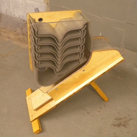
The machine comprises an array of equally shaped twisted rotors with parallel axes. The rotors constitute the walls of sealed cavities or working chambers, which move axially from one end of the array to the other in response to synchronized rotor rotation. The cavities may change their volume during their travel and thereby compress or expand the air enclosed. The rotors do not touch one another to avoid wear and friction, but the gaps are narrow enough to keep the loss of gas neglectable above a certain rotational speed. Below is a simple RPA air compressor with six rotors shown in three different sections. Note how the cavities develop and move and change their volume and finally vanish.
This is a Stirling engine based on the RPA. The middle sections of the rotors are inside an oven, they are hot. The ends of the rotors are outside and cold.
The transparently shown rotors can, but don't need to be made of glass. The rotors are actually hollow, squashed tubes.
Between the rotors there is air enclosed. When the rotors orbit, the enclosed air oscillates between the hot and the cold sections, and it is also being compressed and expanded. It performs a Stirling process and generates useful power.
The novel design overcomes a grave drawback of conventional Stirling engines, namely the inefficient heat transfer to and from the working gas by conduction in heat exchangers. The RPA does not have this problem, because it transports heat by intermediately storing it on its moving surfaces, which alternatingly are in contact both with the working gas and then with the surrounding atmosphere. The materials to be used are no longer required to be good heat conductors, but can instead be better at withstanding high temperatures, which in turn allows achieving better thermal efficiencies with the machine. Moreover, one can expect that power control is easier.
More information is in the documents below.
Stirlingmotor_mit_umlaufenden_Drehkolben.pdf (German) ...
Drehkolben-Stirlingmotor_mit_dynamischer_Abdichtung_und_dynamischer_Aufladung.pdf (German) ...
Ofen_fuer_einen_Drehkolben-Stirlingmotor.pdf (German) ...
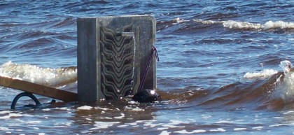
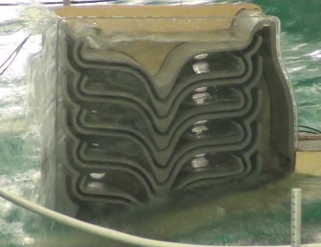
This is a wave-driven drainage pump with no moving parts. It can cheaply be made of concrete.
The shown device pumps rain water from below sea level (small waves) into the sea (big waves). The left side is an OWC-type wave chamber whose oscillating air pressure drives the cascade of artesian wells on the right side. Given enough basins and a large wave chamber, the water can, in principle, climb to any height.
More information is in the documents below.
Below a picture from testing a protype:
Here is a video:
wpum_209.mov (37 MB, QuickTime, best) ...
wpum_209.avi (25 MB, Windows Media) ...
wpum_209.mpg (8.4 MB, small) ...
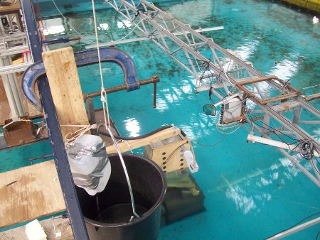
I have tested a wave pump prototype at the Hydraulics and Maritime Research Centre (HMRC) in Cork, Ireland, under MARINET funding. A detailed report is here:
Wave_Pump_Optimization_Study.pdf ...
Below are some pictures.
A less scientific invention. But helps saving money when traveling.
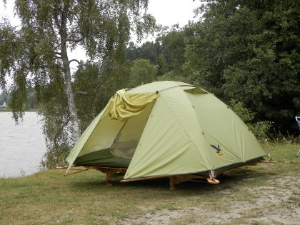
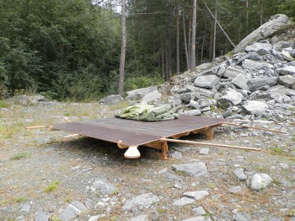
The portable tent platform makes it possible to build a tent well above humpy or sloping ground, especially when traveling with a car and off the designated campsites. Together with an ordinary camping tent it constitutes a cheap and space-saving alternative to a campmobile, or even to a roof tent. It can be packed densely enough to be kept in the narrow cellar of a city apartment.
The tent platform is being assembled from multiple parts, which are carried in a frame on the car roof. The assembly takes only a few minutes. The tent platform has height-adjustable feet. Unevenness, water, dirt and bugs are being kept under and outside the tent. The tent platform has multiple extensions to fasten the tent on, which make it unnecessary to drive tent pegs into the ground. Erecting the tent becomes easy even on hard ground such as rock or asphalt.
The tent platform can be manufactured in any better carpenter's workshop or furniture factory. It is made of varnished plywood and a few standard screws.